
Transitioning from a prototype to mass production can be challenging. This is the stage where your design truly comes to life. That’s why focusing on PCBA design for manufacturability is crucial. Without this consideration, you may encounter issues such as errors or delays. Did you know that 3D printing can produce prototypes in just one day for $100? Collaborating with manufacturers early in the process helps identify problems and rectify errors. It also saves costs by preventing significant design changes down the line. Thoughtful planning and effective tools ensure that design and production work harmoniously together.
Key Takeaways
Design with easy manufacturing in mind to prevent expensive errors.
Work with manufacturers early to find and fix problems.
Test prototypes carefully to spot issues before making many units.
Use PCB design tools that help teamwork and follow simple rules.
Plan and check your design early for a smooth production shift.
Understanding the Transition Process
Key steps to move from prototype to mass production
Switching from a prototype to mass production takes several steps. Each step ensures your design is ready for large-scale production. Here’s a simple guide:
Component Ordering: Get parts from reliable suppliers. Check their stock and confirm they can handle small orders. This prevents future delays.
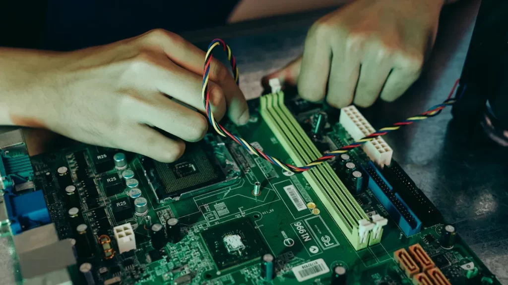
Assembly: During prototyping, assemble parts by hand. Focus on applying solder paste correctly and placing components carefully. Use proper heat to secure them.
Quality Testing: Test each prototype for problems like short circuits or bad soldering. Run special tests to meet specific needs.
After these steps, finalize materials, invest in tools, and do trial runs. These help improve your design and ensure smooth production before scaling up.
Common problems during the transition and how to fix them
You may face challenges during this process. Common problems include unclear roles, late testing, and poor communication. These can cause costly mistakes or missed deadlines.
To solve these issues:
Assign roles early. Everyone should know their job.
Hold regular meetings to keep the team updated.
Test often and early. Finding problems sooner saves time and money.
By working together and communicating well, you can avoid many problems that slow down projects.
Why planning and validation are important early on
Planning and validation are key when preparing for mass production. Early validation, like the production validation test (PVT), checks if your design is ready for large-scale production.
Evidence Type | Description |
|---|---|
PVT Stage Importance | Proves your design can be made in large amounts with good quality. |
Mock Production Run | A practice run to find and fix process problems before full production. |
Potential Issues | Spots problems like high costs or long wait times early on. |
Planning ahead and validating your design helps avoid surprises and makes the production process smoother.
Design for Manufacturability (DFM) Principles
Picking and Getting Components
Choosing the right parts is very important in PCBA design. It’s not just about finding parts that work. You also need to check if they are easy to buy. Think about whether they’ll still be available when you make more products. Imagine using a part that’s no longer made. This could slow down your whole project.
To make better choices, focus on these three things:
Technical needs: Make sure parts meet electrical rules, fit well, and work reliably.
Supply chain needs: Pick parts with many suppliers, short wait times, and steady stock.
Compliance needs: Check for required certifications and eco-friendly standards, especially for special industries.
Here’s a simple guide to help you:
Category | Key Points |
|---|---|
Technical Needs | Electrical rules, Size limits, Reliable performance, Quality checks |
Supply Chain Needs | Many suppliers, Stock status, Short wait times, Cost limits |
Compliance Needs | Certifications, Eco-friendly rules, Industry-specific needs |
By thinking about these, you’ll avoid problems and keep your design on track.
Making Layouts Easy to Build
Your pcb layout isn’t just about connecting parts. It’s also about making production easier. A good layout lowers mistakes, speeds up building, and saves money. Keep trace lines short and leave enough space between parts. This helps signals flow better and avoids interference.
Think about how parts will be put together. Place them to make soldering and checking easier. For example, group similar parts to help machines work faster. Tools like EDA software can show problems before production starts.
Why DRC and DFA Matter
Skipping a design rule check (DRC) is like walking blindfolded—you’ll face problems. DRC makes sure your pcb layout follows rules like trace size and spacing. It’s a simple way to avoid costly mistakes during production.
Design for assembly (DFA) goes further. It makes your circuit easier to build. For example, use common part sizes and avoid tricky designs. Simulations can test how parts fit before production starts.
By using DRC and DFA, your design will work well and be ready for mass production.
Top PCB Design Tools for Easy Manufacturing
Altium Designer: Advanced Features for PCB Design
Altium Designer is one of the best PCB tools. It has advanced features that make designing easier. Its interface is simple and easy to use. You can also see your designs in 3D before production starts.
This tool is great for teamwork. You can share designs and work together smoothly. However, it costs more than other tools. Small businesses might find it pricey, but it’s worth it for its features and reliability.
Here’s a quick look at its pros and cons:
Pros | Cons |
|---|---|
Easy-to-use interface | Costs more than other tools |
3D design preview | Expensive for small businesses |
Team collaboration features |
If you want advanced tools and can afford it, Altium Designer is a great choice.
OrCAD: Better PCB Layout and Signal Flow
OrCAD is another excellent tool for PCB design. It helps improve signal flow and makes layouts easier. It ensures your designs meet manufacturing standards.
OrCAD is great for handling complex designs. It works well for high-speed designs where signals must stay clear. It also supports many CAD formats, making it flexible for different projects.
To use OrCAD effectively:
Watch out for errors in Gerber files.
Check tolerances to avoid mistakes in production.
Use CAD formats that fit your design needs.
OrCAD is a solid choice for improving layouts and signal flow.
KiCad: Free and Flexible PCB Design Tool
KiCad is a popular open-source PCB tool. It’s free, so anyone can use it. Even though it’s free, it has many useful features for manufacturing.
KiCad is great for making prototypes. For example, 81 hardware designs in the PCB Prototyping Catalogue were made with KiCad. This shows it works well for real projects.
Why choose KiCad?
It’s free, so no need to pay for licenses.
It supports advanced designs like HDI and micro-BGA.
A strong community offers guides and help.
KiCad proves you don’t need expensive tools to create great PCB designs.
Autodesk Eagle for easy-to-use PCB design
If you’re new to PCB design, Autodesk Eagle is a great choice. It’s simple and flexible, making it popular with beginners, small businesses, and schools. The interface is easy to understand, so you can start designing without stress. Whether you’re making schematics or layouts, Eagle makes the process smooth.
Why people like Eagle:
It’s beginner-friendly. The tools are simple and help you learn fast.
Schools use it to teach circuit design because it’s easy to use.
It’s great for quick prototypes. Hobbyists and small businesses love this feature.
Eagle is reliable for creating schematics, layouts, and basic simulations. It works well for both simple and advanced projects. Its popularity with hobbyists and small businesses shows how effective it is.
Tip: If you’re just starting, Eagle is a great way to learn PCB design while keeping your projects ready for production.
Cadence Allegro for advanced designs and better production
For complex PCB designs, Cadence Allegro is a top tool. It’s made for professionals handling detailed projects. From high-speed circuits to multi-board systems, Allegro has the features to manage it all while improving production.
What makes Allegro special:
Teamwork Made Easy: Teams can share updates and work together smoothly.
Accurate Designs: It catches mistakes early with advanced checks and simulations.
Handles Complex Systems: It combines digital, analog, and RF parts for tough designs.
Real examples show Allegro’s power. OLogic fixed EMI issues using Cadence tools. Meta Platforms improved a multi-board system with rigid-flex PCBs. These cases prove Allegro helps solve tough problems and improves production.
The software also supports multiphysics simulation. This is important for solving tricky electronic design challenges. Whether you’re working on high-speed circuits or improving power flow, Allegro gives you the tools to succeed.
Pro Insight: For high-speed or multi-board projects, Allegro’s advanced tools ensure precision and efficiency.
Optimized Routing for High-Speed Designs
Routing in high-speed PCB designs is more than connecting parts. It ensures signals move smoothly without interference or distortion. Let’s learn how to achieve this using simple techniques and tools.
Techniques to keep signals clear in high-speed designs
Signal clarity is very important in fast circuits. Without it, signals can weaken or fail. Use these tips to keep signals strong:
Reduce noise: Noise like random changes can harm signals. Keep traces short and avoid sharp turns to lower noise.
Fix skew: Skew happens when signals arrive at different times. Match trace lengths for paired signals to fix this.
Balance signal timing: Make sure high and low signals last the same time. This improves signal quality.
Lower errors: Fewer errors mean better signals. Simulate your design early to predict and fix problems.
Simulations are helpful. Pre-layout simulations check signals before the design is final. Post-layout checks test the finished board. Both steps ensure your design works well.
Tip: Always include electromagnetic (EM) models in simulations. This makes signal testing more accurate.
Tools to manage interference and signal flow
Interference and mismatched signal paths are common problems. Interference happens when nearby traces affect each other. Mismatched paths can cause signals to bounce back. Here’s how to solve these:
Use tools like SPICE to predict and fix interference.
Match trace paths with signal analysis tools to stop bouncing signals.
Test for interference by checking trace spacing. Add ground planes to reduce it.
These tools and methods make your design stronger and ready for production.
Why stable power is key in high-speed PCBs
Stable power is as important as clear signals. Without it, even good routing won’t work. Here’s why power stability matters:
Power affects signals. Bad power delivery adds noise and lowers signal quality.
Use capacitors to keep power steady. They help maintain low resistance for signals.
Plan your PCB layers carefully. A good layer setup reduces resistance and improves power flow.
By checking both power and signal stability, your design becomes more reliable. Fixing problems early saves time and money during production.
Pro Insight: Use advanced routing tools to improve both power and signal flow. These tools make tough tasks easier and boost performance.
Collaboration with Manufacturers
Why working with manufacturers early is helpful
Involving manufacturers early can save both time and money. When you work with them from the start, they share useful advice. They can find problems before they become expensive mistakes. For example, they might suggest better parts, assembly methods, or workflows. This helps improve your design for easier production.
Starting early also improves teamwork. You’ll understand what they can and cannot do. This avoids surprises later. It also builds trust, making the process smoother. Teams that collaborate early often finish faster and with fewer errors.
Tip: Talk to your manufacturer as soon as your prototype is ready. Their advice can greatly improve your design.
Finding production problems early in the design stage
Catching problems early saves time and money. Using Design for Manufacturing (DFM) rules helps you spot and fix issues before production starts. For example, DFM ensures your design matches what manufacturers can do. This reduces mistakes and makes your product more reliable.
Here’s why fixing issues early helps:
It makes production easier and lowers costs.
It improves quality by solving design problems.
It reduces mistakes, so your product works better.
Manufacturers also study problems to improve future designs. They may suggest changes to layouts or parts to make production smoother. This saves time and helps teams communicate better.
Pro Insight: Regular design reviews with your manufacturer can reveal hidden problems. Use these meetings to improve your design and production process.
Making sure your design fits manufacturing processes
Your design must match what your manufacturer can handle. If it doesn’t, you might face delays or extra costs. For instance, some manufacturers are skilled in advanced methods like HDI or micro-BGA. If your design needs these, make sure they have the right tools and skills.
Compatibility also includes using the right tools. Many manufacturers use tools to handle design changes and unique shapes. Without teamwork, mismatches can happen, causing delays and rework.
To ensure compatibility:
Share detailed design files early, including specs and tolerances.
Discuss production steps to set clear expectations.
Use tools to predict and fix design challenges.
By working closely with your manufacturer, your design will fit their process perfectly. This leads to faster production and better results.
Note: Manufacturers often use dashboards to track analytics. Work with them to use these tools and improve your design’s success.
Testing and Quality Assurance
Why testing is crucial during prototyping
Testing your prototype is like checking its health. It ensures the PCBA works properly before mass production. Skipping this step can cause expensive problems later. Careful testing helps find issues like weak signals, power problems, or bad connections early.
Here are some important testing methods:
Testing Methodology | What It Does |
|---|---|
Functional Testing | Checks if the PCB works as planned. |
Signal Integrity Testing | Uses tools to find signal problems like noise or delays. |
Data Communication Testing | Tests data flow using protocols like I2C, SPI, or UART. |
Analog Circuit Testing | Measures input/output and noise with special equipment. |
Troubleshooting Common Issues | Finds and fixes problems like power loss or noisy signals. |
These tests make sure your prototype is strong and ready for the next steps.
Important quality checks for mass production
When making many units, quality checks are very important. They ensure every product meets high standards. You don’t want mistakes to go unnoticed, right?
Here’s what to focus on:
Design Checks: Review files and run DFM checks to avoid mistakes.
Material Inspection: Check materials like copper and boards for strength.
Production Standards: Confirm processes are controlled and traceable.
Testing Procedures: Run electrical and environmental tests for reliability.
Emma Lu, a manufacturing expert, says custom tests can find problems early. This ensures your product is high-quality and ready for production.
Reports like Material Inspections, PCB Checks, and X-ray Reports confirm your product’s strength and compliance. These steps ensure consistency and dependability.
Using automated tools for better testing
Automated tools make testing faster and more accurate. They save time and reduce mistakes. Imagine a tool that not only tests your PCBA but also shows problems right away. Sounds helpful, right?
Here’s how these tools work:
Testing Method | What It Does | Benefits |
|---|---|---|
In-Circuit Testing | Automatically checks during production. | Quick tests, accurate problem detection, and easy fixes. |
Functional Testing | Simulates real-world use to check performance. | Ensures the system works as designed. |
Automated Test Program Generation | Creates test programs automatically. | Saves time and makes testing complex boards easier. |
Using these tools simplifies testing and ensures your PCBA is ready for production. It’s a smart way to save time and keep quality high.
Tip: Start using automated testing early. It’ll make mass production much easier.
Moving from prototype to mass production needs careful planning. A design focused on manufacturability is key. Advanced PCB tools help find problems early. They save time and match your design to production needs. Features like 3D modeling and teamwork tools prevent mistakes and improve collaboration.
Start early with tools that check designs and improve layouts. Work with manufacturers to make sure your design fits their process. These steps make production smoother and save money.
Tip: Pick PCB tools that follow DFM rules and support teamwork. This makes your design better and ready for production.
FAQ
What are the most popular tools for PCB design?
Tools like Altium Designer, OrCAD, and Cadence Allegro are common. They help improve layouts and make designs easier to produce. Free tools like KiCad and Autodesk Eagle are great for beginners or small projects.
Can free PCB tools work for professional designs?
Yes, they can! KiCad is free but supports advanced features. It handles designs like HDI and micro-BGA layouts. Many engineers use it for prototypes and small productions.
How do I pick the best tool for my project?
Think about your project’s size and budget. For complex designs, Cadence Allegro is a good choice. If you need a free option, KiCad offers strong features without extra cost.
Why is it important to design for manufacturability?
Manufacturability makes production faster and avoids mistakes. It lowers costs and prevents delays. Using popular tools helps follow rules and create better layouts.
How can beginners learn PCB design?
Start with free tools like Autodesk Eagle or KiCad. They are easy to use and have online guides. Begin with simple circuits and slowly try harder designs.
See Also
Boosting PCBA Production Speed While Maintaining High Quality
Expert Techniques for Achieving Superior Quality in PCBA Manufacturing
Ensuring Authenticity: Strategies for Reliable PCBA Components
Understanding the Key Differences Between Prototype and Production PCBs