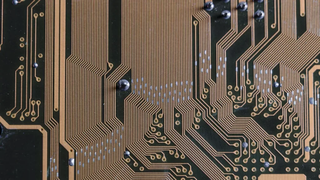

The IIoT sensor node PCBA manufacturing process plays a crucial role for factories. It enables the efficient collection and sharing of data in real time, allowing industries to monitor operations more effectively and make data-driven decisions. As factories increasingly embrace digital transformation, the demand for smarter PCBs with integrated sensors continues to grow. By 2025, advancements like 5G will enhance connectivity, making these solutions even more impactful. In 2022, there were 12.2 billion IoT devices globally, and this figure is projected to rise to 25.44 billion by 2030. As a result, IIoT sensor node PCBA manufacturing has become more critical than ever to meet the needs of this expanding market.
Key Takeaways
Save energy to make batteries last longer and cut costs. Pick parts that use less power and manage energy smartly.
Build with parts that can be swapped or added easily. This helps update and change the design for future needs.
Use strong communication tools like LoRa to send data far. Make sure it works with different networks for better connections.
Make devices tough by using strong materials and testing well. This helps them survive in rough work environments.
Learn about rules and certifications for the industry. This earns customer trust and follows safety and quality rules.
Key Points for Making an IIoT Sensor Node PCBA
Creating an IIoT sensor node PCBA needs good planning. Every choice affects how well your device works and lasts. By focusing on power use, growth options, and communication, you can build a strong device for industrial use.
Saving Power and Using Energy Wisely
Using less power is very important for IIoT sensor nodes. This is especially true for devices in faraway or hard-to-reach places. Your device should use as little energy as possible but still work well. This helps batteries last longer and lowers repair costs.
To save power, pick parts that have energy-saving features. For example, microcontrollers with sleep modes or sensors that turn on only when needed can cut energy use. Also, good power circuits and layered PCB designs help stop energy waste.
Real-life examples show why saving power matters. Fitness trackers use low-power parts to work well in small sizes. Industrial IoT devices use smart cooling and power-saving tricks to stay reliable in tough conditions. These examples show how saving power makes devices last longer and work better.
Growing with Industrial Needs
Making your design easy to upgrade is very important. Your device should handle future changes without needing a full redesign. This keeps your device useful as industrial needs grow.
To make upgrades easier, think about modular designs. Modular nodes let you add or swap parts quickly. For example, you can add new sensors or update communication parts without starting over. This saves time and money while keeping your device flexible.
Studies show how helpful scalable designs are. Advanced models like T-YOLOv5 have improved detection and accuracy. These examples show how flexible systems can handle tough industrial tasks and improve over time.
Communication for Custom Sensor Systems
Good communication is key for custom sensor systems in IIoT. Your sensor node must send data reliably to other devices and systems. Picking the right communication method makes everything work smoothly.
Popular methods like LoRa are great for long-distance, low-energy communication. LoRa lets your sensor send data far away while using little power. This is helpful in big factories or outdoor areas where wires are hard to use.
When designing your PCBA, make sure it works with different communication methods. This helps your sensor system connect with many devices and networks. Doing this improves how well your IIoT device works overall.
Environmental durability and reliability
Making sure your IIoT sensor node PCBA works in tough places is important. These devices often face extreme heat, cold, moisture, dust, and shaking. Building them to last helps them work well and stay useful longer.
To make them durable, pick materials and parts that handle stress. For example, conformal coatings keep out water, dust, and chemicals. Also, use parts that work in both very hot and very cold temperatures.
Testing is key to check if your PCBA is strong and reliable. Factories use tests to meet industrial rules. These include looking for surface problems, checking how well things stick, and using machines to find flaws. Stress tests, like heating and shaking, copy real-life conditions to ensure long-term use.
Here’s a simple table of common tests and their uses:
Testing Method | What It Does | Why It’s Used |
|---|---|---|
Accelerated Life Testing (ALT) | Checks how long PCBAs last under extra stress. | Used in cars, planes, and gadgets to ensure they work well. |
Mechanical Testing | Tests if PCBAs can handle shaking and temperature changes. | Makes sure they don’t break under physical stress. |
Electrical Testing | Checks if PCBAs work properly in different situations. | Ensures they function well in real-world use. |
For example, car control units use ALT to find weak solder joints from heat changes. Plane PCBs are tested for extreme heat and shaking. Even phones go through heat tests to make sure signals stay clear.
By adding these tests to your PCBA process, you can make devices that last in tough places. This lowers repair costs and keeps your devices working well in hard conditions.
Step-by-Step Process to Design and Deploy IIoT Sensor Node PCBA
Understand system needs and make a simple block diagram
First, figure out what your IIoT sensor node needs. Think about the data it will collect, where it will work, and how it will connect to other devices. For example, if it tracks temperature in a factory, pick sensors that handle heat and moisture well.
After listing the needs, draw a block diagram. This diagram shows how parts like sensors, microcontrollers, power, and communication modules connect. It helps you see how everything works together and makes planning easier.
Tip: Use tools like Fritzing or KiCad to draw diagrams. These tools are easy to use and let you make quick changes.
Pick the right parts (microcontroller, sensors, communication modules, power)
Choosing good parts is key to building a strong sensor node. Start with the microcontroller. Pick one that saves power and has enough speed for your tasks. For instance, STM32 microcontrollers are energy-efficient and powerful.
Next, choose sensors based on the data you need. If you’re tracking vibrations, use sensitive accelerometers. For temperature, pick thermocouples or digital temperature sensors.
Communication modules are also important. In big factories, LoRa works well for long distances. For smaller areas, Bluetooth or Wi-Fi might be better.
Finally, pick a power source that fits your needs. Battery-powered nodes need energy-saving parts. Wired nodes can use direct power.
Note: Modular designs let you easily change parts later. This keeps your sensor node useful as technology improves.
Plan the PCB layout carefully
Designing the PCB layout takes careful thought to make it work well. Start by setting design rules like trace widths and spacing to avoid problems during manufacturing. Place parts smartly to make wiring easier and reduce signal issues.
Group similar parts together. For example, keep sensors close to the microcontroller to shorten wires and improve signals. Use inside layers for power and ground to keep signals clean.
Here’s a table of key PCB design steps:
Step | What to Do |
|---|---|
1 | Set design rules to avoid manufacturing problems. |
2 | Place parts carefully for easy wiring and good signals. |
3 | Use inside layers for power and ground to keep signals clean. |
4 | Test the layout to make sure it works as planned. |
Tip: High-speed circuits need extra care with wiring and vias. Follow best practices to keep signals strong and reliable.
By following these steps, you can design a PCB that works well and lasts long. This ensures your sensor node is ready for production and use.
Keep Heat and Structure in Check
Managing heat and structure is key for your IIoT sensor node PCBA. Too much heat or weak parts can cause big problems. These include bad performance, broken components, or the whole system failing. Fixing these issues early makes your device strong and reliable.
Handling Heat the Right Way
Electronics get hot when they work. If heat builds up, it can harm parts like sensors and microcontrollers. To stop this, you need smart ways to manage heat.
Here are simple ways to deal with heat:
Pick Heat-Friendly Materials: Use materials like copper that spread heat fast.
Add Heat Vias: Place small holes filled with metal near hot parts. These move heat to cooler areas of the PCB.
Separate Hot and Sensitive Parts: Keep heat-sensitive parts away from things like voltage regulators.
Use Fans or Heat Sinks: For devices that use lots of power, add fans or heat sinks to cool them.
Tip: Try tools like ANSYS to see how heat spreads on your PCB. This helps you spot hot areas before making the device.
Fixing Structural Problems
Your PCB must fit well in its case and handle stress. If not, it might break, shake loose, or cause short circuits.
Follow these steps to avoid structural issues:
Make the PCB Fit Well: Design it to fit neatly in its case. Avoid odd shapes that make assembly hard.
Strengthen Screw Areas: Add support around screws to stop cracks during setup.
Use Strong Materials: Choose tough materials like FR4 for the PCB base.
Stop Vibration Damage: Secure heavy parts with glue or brackets to keep them in place.
Balancing Heat and Structure
Managing heat and structure together takes planning. For example, adding a heat sink might make the PCB taller, which could affect its fit. To fix this, you can:
Use flat heat sinks or pads.
Change the case design to fit cooling parts.
Pick smaller parts that don’t get too hot.
Note: Test your design in real-world conditions. Check how it handles heat and stress to make sure it works well.
By managing heat and structure, your device will work better and last longer. This step is vital for making strong IIoT sensor node PCBA devices that meet industry needs and handle tough conditions.
Manufacturing and Prototyping for IIoT Sensor Nodes
Prototyping and Improving the Design Step by Step
Making a prototype is an important part of building IIoT sensor nodes. It helps you test your design, find problems, and fix them before making many units. Start by creating a working model using tools like breadboards or kits. These tools let you quickly build and test your circuit without finalizing the design.
After building the first prototype, test it in steps. Check important things like how much power it uses, how well it communicates, and if it can handle tough conditions. Each test gives useful information to make it better. For instance, if your sensor gets too hot, you can change the PCB layout or add cooling parts like heat sinks.
Tip: Write down every change you make. This helps you track progress and avoid repeating errors.
Making the Design Easy to Manufacture (DFM)
Using DFM ideas makes your IIoT sensor node easier and cheaper to produce. A good design for manufacturing lowers costs and improves quality. Here are some simple DFM tips:
Use fewer parts to save money.
Pick common parts to save time and ensure quality.
Design parts that can be easily swapped or upgraded.
Combine parts to reduce the total number needed.
Avoid screws or glue to make assembly simpler.
Make sure the design is easy to build to cut costs.
Reduce handling during assembly to speed up production.
For example, modular designs not only make manufacturing easier but also allow for quick updates later. Following these tips helps you make a better product faster and at a lower cost.
Picking the Best PCB Maker and Assembly Team
Choosing the right company to make and assemble your PCBs is very important. Look for companies with experience in IoT PCB projects. Check if they can handle small, detailed designs. Advanced tools ensure accurate and consistent results.
Certifications like ISO 9001 and IPC show they care about quality. A history of delivering reliable products is also key. Make sure they use strong testing methods like In-Circuit Testing (ICT) and Environmental Stress Testing (EST). These tests check if your product works well in real-life situations.
Note: Working with a trusted manufacturer lowers risks and ensures your sensor nodes meet industry rules.
Following Industry Standards and Getting Certifications
Making IIoT sensor node PCBAs needs following industry rules. These rules make sure your product is safe, works well, and fits industrial needs. They also help you earn customer trust and follow laws in different places.
First, find out which certifications your product needs. For IIoT devices, some important ones are:
UL Certification: Checks for electrical safety to stop problems like overheating. This is very important for devices used in factories.
CE Marking: Needed for products sold in Europe. It shows your product meets health, safety, and environmental rules.
RoHS Compliance: Limits harmful materials in electronics, making your product safer for the planet.
FCC Certification: Required in the U.S. for devices with wireless features. It ensures your product doesn’t mess with other electronics.
Tip: Learn about needed certifications early. This avoids delays and costly changes later.
To meet these rules, follow good design and manufacturing steps. Use certified parts like UL-approved microcontrollers or RoHS-safe sensors. Work with skilled manufacturers who know how to make certified PCBAs. They can guide you and help avoid mistakes.
Testing is very important for meeting standards. Do safety tests like checking insulation and strength for UL rules. Test for electromagnetic compatibility (EMC) to pass FCC or CE standards.
By focusing on these rules, your product will meet industry needs and stand out in the market. This keeps users safe and builds a strong name for your brand.
Testing and Validation for Reliable IIoT Sensor Nodes
Debugging Hardware and Testing Functions
Debugging and testing make sure your IIoT sensor node works well. These steps find and fix problems in hardware or software before use. Functional testing checks if each part does its job and connects properly.
Tools like JTAG boundary-scan testing can make debugging easier. For example, Reptron Manufacturing Services cut their testing time by 1,457% using this tool. This method saves both time and money.
Here’s a table of common tests and what they do:
Test Type | What It Does |
|---|---|
ICT Test | Checks connections, voltage, current, and noise in circuits. |
FCT Test | Tests the whole PCBA to find hardware or software problems. |
Fatigue Test | Measures how long the device works before failing. |
Harsh Environment Test | Tests how the device handles extreme conditions. |
Aging Test | Checks for failures during long-term use. |
Using these tests ensures your sensor node is strong and ready for tough jobs.
Testing for Tough Environments
IIoT sensor nodes must survive in harsh places. These devices face heat, cold, moisture, dust, and shaking. Environmental testing checks if they stay reliable in such conditions.
Tests like thermal cycling and vibration analysis copy real-world situations. For instance, harsh environment tests see how devices work in very hot or cold temperatures. Accelerated life testing (ALT) predicts how long they will last under stress.
Tip: Protect your PCBA with conformal coatings. These keep out moisture and dust, making devices last longer.
By doing these tests, you can lower failure rates and extend the life of your devices.
Checking Reliability and Device Lifespan
Reliability testing checks if your IIoT sensor nodes stay stable over time. This is important because these devices often work in unpredictable places. Metrics like failure rate and reliability-over-time (ROPT) help measure long-term performance.
Here’s a table of reliability metrics and their meanings:
Metric Type | What It Measures |
|---|---|
Standard Metrics | Tracks reliability, failure rate, and recovery ability. |
Non-standard Metrics | Measures trust factor and ROPT for individual device stability. |
Real-time Metrics | Checks data quality using metrics like availability and accuracy. |
Frameworks like the Trust Factor Model show how the environment affects reliability. By studying these metrics, you can find weak spots and improve your design.
Note: Always test devices in real-world conditions. This ensures they meet safety standards like UL certification.
By focusing on reliability and lifespan testing, you can create IIoT sensor nodes that work well and gain user confidence.
Final quality checks and certifications
Final quality checks make sure your IIoT sensor node works well and meets rules. Certifications prove your product is safe and follows laws, giving customers trust in its quality. Skipping this step can cause problems like failures or legal trouble.
Start by matching your product to important compliance rules. These rules cover safety, cybersecurity, and quality. Here’s a table of key certifications and what they mean:
Compliance Standards | What It Covers |
|---|---|
ISO 9001:2015 | Quality management systems |
21 CFR Part 11 | FDA rules for electronic records |
NIST Cybersecurity Framework | Cybersecurity guidelines |
GDPR | EU data protection rules |
NEC | Electrical safety standards |
OSHA Regulations | Workplace safety rules |
Privacy Legislation | Canadian privacy laws |
Industry Standards | General compliance rules |
Health and Safety Regulations | Canadian workplace safety laws |
Data Protection Regulations | Canadian data privacy rules |
Quality Control Standards | Rules for keeping product quality |
Cybersecurity Requirements | Canadian cybersecurity rules |
Product Certification Regulations | Rules for certifying products |
Data Retention and Destruction Requirements | Rules for managing and deleting data |
Testing is very important for quality checks. Functional tests make sure your device works as planned. Environmental tests check if it can handle tough conditions. For example, thermal cycling tests see if your sensor can survive big temperature changes. Fatigue tests measure how long it lasts with constant use.
Real-life examples show why certification matters. In Massachusetts, a factory used IIoT sensors to improve product quality. In Michigan, a car parts maker lowered defects by tracking quality with sensors. A pharmaceutical company in California followed rules by using IIoT devices to monitor production.
Tip: Work with certified testing labs to make certification easier. These labs help you meet rules like ISO 9001 or FDA standards quickly.
By focusing on quality checks and certifications, your IIoT sensor node will be safe, reliable, and follow rules. This step protects your brand and builds customer trust.
Future Trends in IIoT Sensor Node PCBA Design and Manufacturing
AI and Edge Computing in Sensor Nodes
AI and edge computing are changing how sensor data is handled. Adding AI to the PCBA allows quick decisions without needing the cloud. This makes your lora IoT sensor node faster and more efficient. For example, AI can spot problems in machines by analyzing data locally. This helps avoid expensive breakdowns.
Edge computing processes data near the source, saving bandwidth. This is helpful for lora networks used in large areas. With edge AI, sensors can work alone, even in places with weak connections.
New Materials for Better Sensor Systems
New materials are improving IIoT PCBAs. Flexible boards and special semiconductors make sensors stronger and better. These materials help manage heat and improve how your lora IoT sensor node works in tough conditions.
Smaller, energy-saving sensors are now possible thanks to advanced materials. These sensors collect accurate data, which is important for 5G and faster communication. Industries need these innovations to keep up with new technology.
Market Value (2023) | Projected Value (2029) | CAGR (%) | Key Drivers |
|---|---|---|---|
$67.9 billion | $92.4 billion | 5.4% | Demand for AVs, EVs, IoT devices, and 5G networks |
Stronger Security for Industrial Sensors
As IIoT devices connect more, security becomes vital. Sensor nodes must protect data from hackers. Features like hardware encryption and secure booting keep devices safe from attacks.
Cybersecurity is now a big part of electronics manufacturing. Adding secure communication to your lora IoT sensor node ensures safe data sharing. This not only protects devices but also earns customer trust.
Tip: Follow the latest security rules to keep your IIoT devices safe from new threats.
Adoption of 6G and Next-Gen Communication Technologies
6G and next-gen communication will change how IIoT sensor nodes work. These new technologies bring faster speeds, less delay, and better connections. They are perfect for use in factories and other industries.
With 6G, data will move up to 100 times faster than 5G. This means IIoT sensor nodes can send and process data almost instantly. For example, factory sensors can quickly alert workers about machine problems. This helps fix issues faster and reduces downtime. The very low delay of 6G also makes robotic systems work smoothly.
Next-gen communication improves systems like lora. Lora is great for long-distance, low-power data sharing. When combined with 6G, it becomes even more powerful. For instance, lora can collect data in faraway places, while 6G processes it super fast. Together, they ensure reliable performance, even in tough industrial areas.
To get ready for these changes, design IIoT sensor nodes to handle future upgrades. Use modular designs so you can easily update communication parts. Also, test your devices to work with both lora and 6G networks. This keeps them useful as industries adopt new technologies.
Tip: Learn about 6G rules and standards early. Being prepared can make your devices stand out in the growing IIoT market.
By using 6G and next-gen technologies, you can build smarter and faster IIoT sensor nodes. These updates will improve industrial monitoring and create new opportunities.
Making an IIoT sensor node PCBA takes careful planning. First, figure out what the system needs. Then, pick the right parts and design a strong PCB layout. Testing makes sure the device works well in tough places. Manufacturing steps, like making prototypes and following rules, help create a good product.
It’s important to balance design, ease of making, and reliability. A smart design lowers costs and makes the device last longer. Keeping up with new ideas, like using AI and 6G, helps your devices stay useful and ahead in the market.
Tip: Check for new industry updates often. This helps improve designs and meet changing needs.
FAQ
What is an IIoT sensor node PCBA?
An IIoT sensor node PCBA is a circuit board used in industrial IoT. It gathers data from sensors, processes it, and shares it with other devices. These nodes are key for tracking and automating factory tasks.
How do you keep IIoT sensor nodes energy-efficient?
To save energy, use parts like microcontrollers with sleep modes. Design power circuits carefully and plan the PCB layout to avoid wasting energy. These steps make batteries last longer and lower repair costs.
Why is modular design useful for IIoT sensor nodes?
Modular design lets you change or upgrade parts easily. This saves time and money. It also helps your device stay updated with new technology or changing factory needs.
What certifications are needed for IIoT sensor nodes?
Key certifications include UL for safety, CE for Europe, RoHS for eco-friendliness, and FCC for wireless rules. These ensure your device is safe, reliable, and trusted by users.
How do you test IIoT sensor nodes for toughness?
Test toughness with methods like heat cycling, vibration tests, and stress testing. These tests copy tough conditions to check if the device works well over time. Testing finds weak spots and makes devices stronger.
Tip: Test your device in real-life settings to meet factory needs.
See Also
Emerging Trends in Smart PCBA Manufacturing for 2025
The Importance of PCBA Manufacturing for IoT Devices Now
Key Trends Influencing Industrial PCB Assembly for IoT in 2025