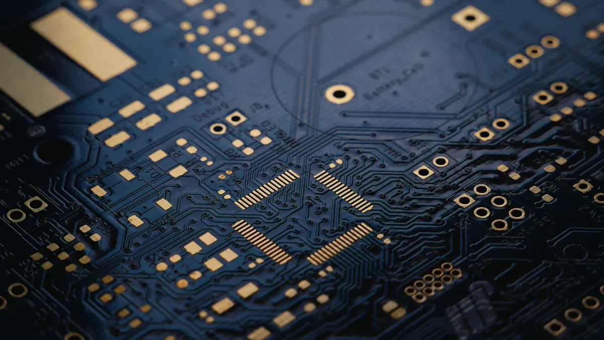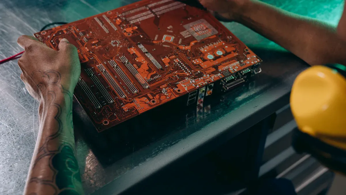
Industrial places often shake and jolt printed circuit boards, making the use of vibration-resistant PCBA for industrial environments essential. These movements can break solder joints and harm parts, especially in cars or factory machines. Skipping vibration-proof PCBs causes more breakdowns, wasted time, and shorter equipment life. To keep them working well, use strong materials, good insulation, and heat protection. Important factors like glass transition temperature (TG) and thermal decomposition temperature (TD) show how tough PCB materials are. Covering parts with special coatings helps hold them steady and handle stress, making them last longer.
Key Takeaways
Pick tough materials that handle heat well to make PCBs last longer in factories.
Arrange parts on the PCB carefully to lower stress and keep them steady during vibrations.
Add thicker layers and supports to stop PCBs from bending or breaking.
Test PCBs using vibration tools and shock machines to check if they can handle real-life use.
Work with makers to design special solutions for vibration resistance needs.
Vibration Challenges in Industrial Environments

Common sources of vibration and electric shock
In factories, machines like motors and conveyors cause vibrations. These movements spread to nearby devices, including PCBs. Vehicles such as forklifts and trucks also create vibrations in factories. Electric shocks happen due to power surges or bad wiring. Both vibrations and shocks make it hard for PCBs to work well. Strong PCBs are needed in places with lots of shaking.
Effects of vibration on PCB performance and lifespan
Vibrations can harm PCBs and shorten their lifespan. They weaken solder joints, especially on small parts, over time. The board bends and flexes, damaging solder and part connections. Research shows vibrations and shocks cause 20% of PCB failures. Most damage happens at the tops of solder joints and fillets. This wear makes PCBs less reliable and raises repair costs.
Real-world examples of vibration-related failures
Real-life cases show why vibration-resistant PCBs are important. In cars, engine vibrations and bumpy roads damage solder joints, causing problems. In factory machines, boards in class 3 products often fail from shaking. These failures stop work and cost money to fix. Knowing these issues helps you design stronger PCBs for tough conditions.
Core Principles for Designing Vibration-Resistant PCBs
Material selection for vibration-resistant PCBA for industrial environments
Picking the right materials is key to making strong PCBs. These materials need to handle heat and stress in tough places.
Thermal Performance: Use materials with high glass transition temperature (Tg) and good heat flow. This helps cool the board and makes it last longer.
Mechanical Strength: Choose materials that are strong and resist breaking. This stops damage from shaking and keeps the board steady.
Cost Considerations: Find a balance between cost and quality. Strong materials may cost more but save money by lasting longer.
Environmental Considerations: Pick eco-friendly materials that reduce waste and follow green rules.
By focusing on these points, you can make PCBs that work well in rough conditions.
Tip: Materials with higher Tg values are great for stopping vibration damage, especially in hot places.
Component placement strategies to reduce stress
Where you put parts on a PCB matters for handling vibrations. Good placement lowers stress and makes the board more reliable.
Evidence | Description |
|---|---|
Proper Spacing | Leave enough space between parts for better heat control. |
Edge Clearance | Keep parts away from edges to avoid damage during making. |
Test Point Accessibility | Place test points smartly for easy checking and fixing. |
Testing under real conditions is important. It checks if the board can handle heat and shaking.
Don’t group parts too close together. Spread them out to lower vibration effects and help with cooling. Keep delicate parts away from areas that shake a lot.
Structural reinforcements, including thicker substrates and stiffening ribs
Making the PCB stronger is another way to fight vibrations. Thicker boards and extra supports help stop damage.
Thicker Substrates: A thicker board bends less, protecting parts and solder joints.
Stiffening Ribs: Adding ribs or supports makes the board stronger and less likely to crack.
Vibration Dampening Layers: Layers that absorb shaking can make the board last longer.
These steps make the PCB tougher and help it work longer in hard conditions.
Note: Extra supports are very useful for boards in moving machines like cars or factory tools.
By using strong materials, smart part placement, and extra supports, you can build PCBs that survive in tough industrial places.
Testing Methods for Vibration Resistance

Key vibration testing standards and protocols
To check if your PCB can handle shaking and shocks, follow testing rules. These rules help test how strong PCBs are in tough conditions. Below is a table of common testing standards:
Standard | Description | Link |
|---|---|---|
IEC 60068-2-27 | Checks how products handle sudden shocks. | IEC 60068-2-27 |
IEC 60068-2-57 | Tests short vibrations using time-based methods. | IEC 60068-2-57 |
IEC 60068-2-64 | Measures product strength under random shaking. | IEC 60068-2-64 |
IEC 60068-2-80 | Tests performance under mixed shaking patterns. | IEC 60068-2-80 |
ANSI C136.31 | Focuses on vibration tests for streetlights and area lights. | ANSI C136.31 |
ASTM D3580 | Tests up-and-down shaking of products. | ASTM D3580 |
ASTM D5112 | Tests side-to-side shaking of products. | ASTM D5112 |
ASTM E756 | Measures how materials reduce shaking. | ASTM E756 |
These rules help check if PCBs can survive shaking and shocks. For example, the MIL-STD-810G rule says no cracks after a 5G shake test. Tests also include extreme heat or cold, shocks up to 150G, and shaking between 10 and 500 Hz.
Tip: Pick the testing rule that fits your product for better results.
Practical testing setups for industrial PCBs
Creating a good testing setup is important for checking PCBs. You can copy real-world conditions to find weak spots. Here are some common setups:
Vibration Tables: These tables shake at different speeds and strengths. They test how PCBs handle shaking.
Shock Test Machines: These machines give sudden hits to test strength.
Environmental Chambers: These chambers mix shaking with heat and humidity. They copy tough conditions PCBs face.
For example, a vibration table can shake from 10 to 500 Hz at 10G+. This shows how heavy machines affect PCBs. Adding environmental chambers checks how PCBs handle both shaking and heat.
Note: Make sure your setup is mounted right to avoid wrong results.
Accelerated life testing for vibration and electric shock durability
Accelerated life testing (ALT) helps predict how long PCBs last in tough conditions. This test uses extra stress, like strong shaking and shocks, to find weak spots.
One ALT example is Highly Accelerated Life Testing (HALT). In HALT, PCBs face hot and cold steps, shaking, and combined stresses. This finds design problems early. For instance, a company found issues during HALT vibration tests. They fixed these problems before making more PCBs.
Using ALT ensures your PCB is strong for industrial use. It saves time and avoids costly failures later.
Callout: Adding HALT to your tests makes PCBs stronger against shaking and shocks.
Advanced Techniques for Better Vibration Resistance
Anti-vibration frames and enclosures
Anti-vibration frames and enclosures make PCBs stronger in tough places. Frames make boards stiffer, raising their natural frequency. This helps them handle vibrations without bending or breaking. Enclosures add extra protection by blocking outside forces.
Frames make PCBs stiffer, lowering damage from shaking.
Tested enclosures work better than regular ones in random vibrations.
Checking how PCBs react to vibrations improves their design.
Using these methods helps PCBs survive in harsh conditions.
Staking materials to hold components
Staking materials keep PCB parts steady during vibrations. These adhesives stick parts to the board, stopping movement and lowering stress. Different adhesives have special uses:
Adhesive Type | Key Features | Use in Vibrations |
|---|---|---|
Epoxies | Strong bonds and resist chemicals. | Good for stressed parts. |
Silicones | Flexible and handles high heat. | Keeps bonds strong during shaking. |
Acrylics | Handles vibrations and temperature changes. | Best for vibrating setups. |
Polyurethanes | Strong and bendable bonds. | Holds light parts during shaking. |
Staking Adhesives | Supports leads and resists vibrations. | Replaces screws in PCB assembly. |
Picking the right adhesive keeps parts safe in shaky places.
Shock-absorbing parts in PCB design
Adding shock-absorbing parts makes PCBs handle vibrations better. These parts lower sudden force impacts, protecting the board and its parts. Common ways include:
Rubber Mounts: Rubber between the PCB and case absorbs shocks.
Damping Layers: Special layers reduce stress from vibrations.
Flexible Connectors: These connectors ease strain on solder joints.
These features keep PCBs working well in tough industrial jobs.
Overcoming Challenges in Vibration-Resistant PCB Design
Balancing cost with performance
Making PCBs for tough places needs smart choices. You must pick strong materials and methods that don’t cost too much. For example, making through-hole PCBs uses 55-60% of the budget on materials. Aerospace and defense industries like through-hole PCBs because they are reliable. But spending too much on materials can slow new ideas by cutting research funds.
Here are ways to save money and keep quality:
Use strong materials to avoid expensive repairs later.
Make boards smaller and lighter to use fewer materials.
Add through-hole parts and fasteners for better strength.
Test boards for shaking and shocks to stop costly problems.
Checking costs and performance shows that smart tools can find defects early. Better processes also make production faster and cheaper. These steps help PCBs work well in tough places without costing too much.
Solution Type | How It Helps PCB Design | Improvement Made |
|---|---|---|
Energy use tracking | Cuts power waste by 19% in medical PCBs without hurting performance | 19% less power waste |
Defect prediction tools | Finds problems early, making designs more reliable | Better defect detection |
Process improvement tools | Makes production smoother and boosts shock resistance | Faster production |
Addressing space constraints in industrial environments
Small spaces in factories make PCB design tricky. Machines often don’t have room for big boards. Smaller boards save space and handle vibrations better. Cutting board size and weight also helps them last longer.
New imaging tools like RGB and hyperspectral imaging help design better boards. These tools study part placement and improve layouts for tight spaces. For example, the PCB-Vision dataset helps recycle old boards and find parts, supporting eco-friendly designs.
To solve space problems:
Avoid thin or long traces that break under stress.
Use bendable connectors to save space and protect solder joints.
Test boards in real setups to check if they fit and work well.
Collaborating with manufacturers for custom solutions
Working with manufacturers helps make PCBs for tough places. They know about materials, part placement, and board supports. Long-term deals with manufacturers often include rules to share risks and ensure materials are available.
When teaming up with manufacturers:
Share clear needs for vibration resistance and small spaces.
Ask for test samples before making lots of boards.
Use their knowledge to find cheaper ways to meet your needs.
Good teamwork with manufacturers helps create strong PCBs that work well in hard conditions without spending too much.
Making PCBs that resist vibrations needs careful planning. Using strong designs and good tests keeps them working longer. For instance, changing the SiF₄ gas analyzer’s PCB cut failures by 57%. It also made it work better and cost less to make. This shows why fixing problems like solder joint breaks early is key.
Getting help from experts finds problems before they happen. Using Design for Reliability (DFR) helps build PCBs that handle shocks and last longer. Focusing on vibration resistance stops failures, saves money, and improves how they work over time.
Tip: Planning well at every step makes PCBs stronger and more reliable for tough jobs.
FAQ
What matters most when designing vibration-resistant PCBs?
Picking the right materials is key. Choose ones with strong mechanical and thermal properties. These features help the PCB survive shaking and tough industrial conditions.
How do you check if a PCB resists vibrations?
Use tools like vibration tables, shock machines, or special chambers. These setups copy real-world shaking, impacts, and temperature changes. Testing shows if the PCB can handle hard environments.
Are thicker PCBs always better for stopping vibrations?
Not every time. Thicker boards bend less and last longer but cost more. You need to balance thickness with material type and part placement.
Can glue help with vibration resistance?
Yes, glues like epoxies or silicones hold parts steady. They stop movement during shaking and protect solder joints. Pick the right glue based on the stress and environment.
Why does part placement matter in vibration-resistant PCBs?
Good placement lowers stress on parts and solder joints. Keep parts away from edges or areas that shake a lot. Spread parts out to cool better and work longer.
Tip: Test your PCB design in fake conditions to find weak spots early.
See Also
Innovative AI Technologies Transforming RSJPCBA Design Processes
Essential Techniques for Achieving Superior PCBA Manufacturing Quality
How to Choose the Ideal PCBA Manufacturer for You
The Role of PCBA in Enhancing Industrial Automation Efficiency
Ensuring Smooth Transition from Prototype to Production in PCBA


