Core requirements for material selection
Low dielectric constant (Dk) with low loss factor (Df)
Key parameters:
Dk stability: Dk fluctuations need to be small as frequency increases (e.g. Rogers RO4350B Dk=3.48±0.05 over 1~40 GHz).
Extremely low Df: Df ≤ 0.003@10 GHz (e.g. Taconic Taconic RF-35, Df=0.0018@10 GHz).
Typical materials:
PTFE base material (polytetrafluoroethylene): Dk=2.1~2.5 for millimeter wave (e.g. 28GHz 5G antenna).
Ceramic filler material (e.g. Rogers RO4003C): Dk=3.38, Df=0.0027, balancing cost and performance.
Modified FR-4 (e.g. Isola I-Tera MT40): Dk=3.45, compatible with conventional FR-4 process.
Thermal stability matched to CTE
Glass transition temperature (Tg): ≥180°C (e.g. Arlon 25N, Tg=220°C), compatible with lead-free soldering.
Coefficient of Thermal Expansion (CTE): Z-axis CTE ≤ 30 ppm/°C, reducing interlayer separation due to temperature cycling.
2. Key Process Challenges and Solutions
Fine Line Processing
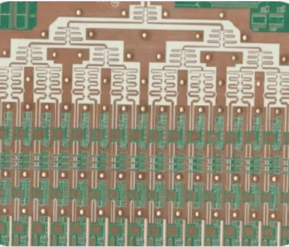
Line width/spacing: ≤3 mil (75 μm) with mSAP (semi-additive method) process to minimize side etching.
Copper foil roughness: ultra-low profile copper (HVLP copper, Ra ≤ 1.5μm), reduced skinning loss (skinning depth δ ≈ 1.3μm@10GHz).
Drilling and Hole Metallization
Laser drilling: for blind holes (hole diameter ≤ 100μm), depth to diameter ratio ≤ 0.8:1 (e.g. 0.1mm hole diameter / 0.08mm depth).
Plating to fill holes: copper thickness in holes ≥25μm, hole resistance <1mΩ, using pulse plating to enhance uniformity.
Surface treatment
Chemical nickel-palladium gold plating (ENEPIG): thickness Ni ≥ 3μm, Au ≈ 0.05μm, suitable for high-frequency welding and oxidation resistance.
Immersion Silver: low-cost solution, anti-sulfide corrosion (storage time <6 months).
3. Typical application scenarios and design cases
5G millimeter wave antenna module
Requirements: 28GHz band, 2GHz bandwidth, insertion loss <1dB/cm.
Design:
Material: Rogers RO3003 (Dk=3.0, Df=0.0013@28GHz).
Transmission line: coplanar waveguide (line width 0.15mm, spacing 0.1mm), ground crossing spacing 0.5mm.
Antenna array: 4×4 patch antenna, feed line impedance 50Ω, radiation efficiency >80% optimized by simulation.
Satellite communication RF front-end
Requirements: Ka-band (26.5~40GHz), extreme temperature resistance (-55℃~+125℃).
Design:
Material: PTFE substrate (Dk=2.2, CTE=16 ppm/°C).
Layer structure: 6-layer hybrid dielectric (HF layer + power layer), blind hole connection to reduce parasitic inductance.
Heat dissipation: embedded copper-tungsten alloy heat sink block (thermal conductivity 180 W/m-K), connected to housing heat sink.



评价
目前还没有评价